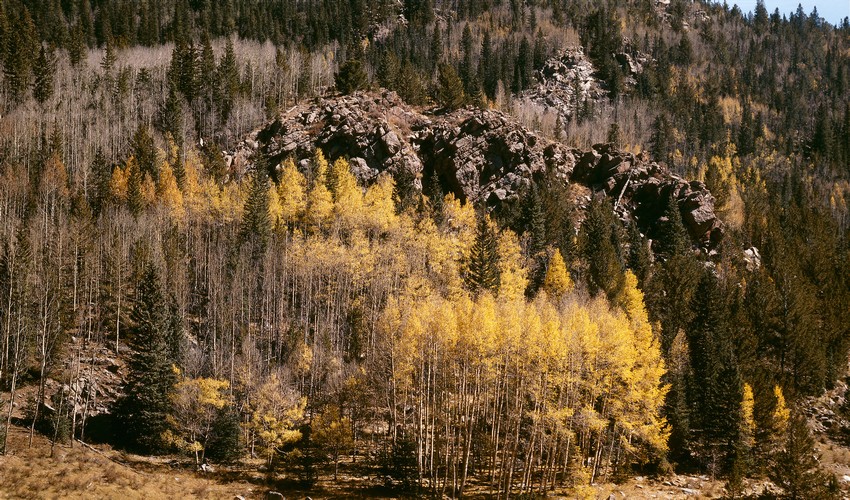
Fall Aspen and Rock Outcrop - An example of half framing, with an aspect ratio just below 1.7 .
For the geologically minded, this is the fracture at the margin of the Pikes Peak granite batholith, along its west side.
One can get a doubling of film use efficiency by doing what I call half framing, withdrawing the dark slide only half way and exposing one end of the sheet of film, and then flipping the sheet around in the holder to later expose the other end.
On one holder that I measured, the opening ("gate" in technical terms) is ~120mm in the long dimension, so half of this is about 60mm or a little less, to allow for some space between the two exposures, and because the film can rattle around a little in the holder.
I make spacers for each holder so that the dark slide is withdrawn just the right amount. Depending on how much the slide goes into the far end of the holder, which is typically something like 5-7mm, the slide will need to be withdrawn 65-72mm from its fully inserted position to reveal the right amount of film. The spacer is designed to do this. In practice I aim for a height of 59½mm in what becomes the short dimension of the half frame exposure.
The long dimension of the resulting half-frame exposure in the holder I measured was 94½mm, which then yields an aspect ratio for the exposure of 1.588 (94½/59½). This is intermediate between 3:2 and 16:9. For exposures made in vertical (or portrait) orientation I don't like to go above about a.r.=1.4, so with this constraint I take the always usable long dimension to be 83.3mm (1.4⋅59½mm), which gives a "bonus" of ~5mm on either end when working in horizontal (landscape) orientation.
The diagonal of a 59½ x 83.3mm frame is 102 3/8 mm, so that would be the focal length of a nominally "normal" lens to use when half framing. A 90mm focal length is then normal-wide, and a 75mm focal length corresponds to wide angle -- about the equivalent of using a 110mm focal length for full frame 4x5. Longer focal lengths then become slight to moderate telephoto lenses.
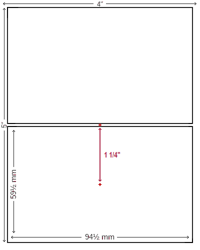
In order to center the optical axis on the exposed area when half framing, one needs to offset it from its normal position, by an amount about equal to one fourth the sheet of film's long dimension, or ~31mm (1¼"). See the layout diagram at right. The way this is done differs for the two possible orientations.
With the camera back in what would be the horizontal orientation for a full sheet, the needed shift for half framing is also in the horizontal direction; the exposure itself will be in vertical orientation (and vice versa). With my camera the maximum possible side shift for either the front or back is ~1", so I have to shift the front one way and the back the other way so it adds up to a total 1¼" side shift. (Photo at right to be added soon shows the camera this way as seen from above.)
With the camera back in the vertical orientation, to get a horizontal orientation for the exposure, the lens shift needed to re-center the optical axis is vertical. And it requires the lens to be dropped, assuming the back's film holder opening is at the top of the camera, since when half framing we're always exposing the other end of the sheet of film. While some cameras may have the capability of dropping the front 1¼", my monorail camera doesn't. (And no bed camera will.) The way around this limitation is to point the camera down and then "re-verticalize" both the front and back using the backward tilts for both until they are again parallel.
With a little simple geometry we can figure out the angle needed for the down-pointing to give a 1¼" vertical offset, which then leaves the rising/lowering front in its nominal or centered position, so one still has the usual range of its movement. This angle will differ depending on the lens' focal length, being steeper for shorter ones. For F=75mm it's 22°, or almost a quarter of a right angle. Without a heavily recessed lensboard this much swing would probably torture the bellows beyond its ability to flex. As it is, this is 50% more swing than the 15° which exceeds what might be called a soft limit on the amount of front backward swing; above this the little spring-loaded ball bearing that engages a small hole in the side support when the front tilt is centered (0°) swings out past the edge of the support. In order to fix this limitation I made a custom right front support allowing (in principle) up to a 25° backward swing, with indents for the ball-bearing marking the amount needed for each of my four shortest focal length lenses (75, 90, 110, and 135 mm's).
©2015-20, Chris Wetherill. All rights reserved. Display here does NOT constitute or imply permission to store, copy, republish, or redistribute my work in any manner for any purpose without prior permission.

Your support motivates me to add more diagrams and illustrations!
